Martensite Formation
Martensite is a hard, brittle form of steel with a tetragonal crystalline structure, created by a process called martensitic transformation. It is named after metallurgist Adolf Martens (1850-1914), who discovered its structure under his microscope during his metallographic research and explained how the physical properties of different types of steel were affected by their microscopic crystalline structures. Martensite commonly is found in tools such as hammers and chisels and in swords.

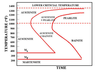
Figure 1 - The martensite is formed by rapid cooling
The martensite is formed by rapid cooling (quenching) of austenite which traps carbon atoms that do not have time to diffuse out of the crystal structure. This martensitic reaction begins during cooling when the austenite reaches the martensite start temperature (Ms) and the parent austenite becomes mechanically unstable. At a constant temperature below Ms, a fraction of the parent austenite transforms rapidly, then no further transformation will occur. When the temperature is decreased, more of the austenite transforms to martensite. Finally, when the martensite finish temperature (Mf) is reached, the transformation is complete.
The martensitic transformation is a diffusionless phase transition in the solid state with a large deviatoric component. What this means shall be illustrated by a simple two-dimensional sketch.

Figure 2 - Two-dimensional sketch of a martensitic transformation from a square lattice a to two variants b and c which differ only in orientation.
Consider in figure 1a a quadratic array of circles, representing the atoms. For some reason this array becomes unstable and distorts to the lattice shown in figure 1b.The distortion shown is large, but the area of the array can remain the same. It is a homogeneous distortion of the original lattice in which an atom does not change its position with respect to its neighbors, it only alters their distances. This is characteristic of diffusionless transformations with large shape changes. For these reasons the transformation can be called deviatoric.

Figure 3 - Temperature dependence of the percentage M of martensite formed during a cooling and heating cycle marked by the arrows. The relevant characteristic temperatures are indicated.

Figure 4 - Relation between length change Dl and applied force F at a temperature T above AF. When the transformation is complete the force increases rapidly again.
Figure 5 - The stacking of close packed planes in an fcc lattice, marked by three different symbols, the large open circles, the larger and the smaller filled circles, corresponding to a stacking ABC. Also shown is a smallest vector a between neighboring holes, and the shortest translation vector b.
Figure 6 - Two unit fcc cells with a smaller body centered tetragonal cell marked in the center (left). By a homogeneous compression in the direction of the arrows and an expansion in the plane normal to it the bcc structure (right) is obtained.
Figure 7 - FCC to BCT
One of the differences between the two phases is that martensite has a body-centered tetragonal (BCT) crystal structure, whereas austenite has a face-centered cubic (FCC) structure. Martensite has a lower density than austenite, so that the martensitic transformation results in a relative change of volume.
Martensite is not shown in the equilibrium phase diagram of the iron-carbon system because it is not an equilibrium phase. Equilibrium phases form by slow cooling rates allowing sufficient time for diffusion, whereas martensite is usually formed by fast cooling rates. Since chemical processes (the attainment of equilibrium) accelerate at higher temperature, martensite is easily destroyed by the application of heat. This process is called tempering. Since quenching can be difficult to control, many steels are quenched to produce an overabundance of martensite, then tempered to gradually reduce its concentration until the right structure for the intended application is achieved. Too much martensite leaves steel brittle, too little leaves it soft.
Equilibrium phases form by slow cooling rates allowing sufficient time for diffusion, whereas martensite is usually formed by fast cooling rates. This process is called tempering. Too much martensite leaves steel brittle, too little leaves it soft. The resulting martensitic steel is extremely hard but very brittle. Thus, the martensite is then heated in a process called tempering, which causes the martensite to transform partially into ferrite and cementite.
Figure 8 - Surface markings due to the formation of martensite plates in Fe-Ni single crystals. The width of the figure corresponds to 4mm of the sample.
The martensitic transformation leaves also characteristic marks on the surface. In figure 8 is shown the surface contrast due to a partial martensitic transformation in an iron-nickel single crystal. The dark bands are the traces of martensite plates that have grown through the sample volume and have intersected with the surface leading to a surface upheaval. The long ones have formed first, and between them shorter ones have appeared whose growth has been impeded by the long ones.
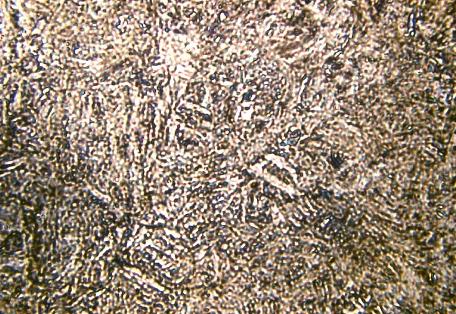
Figure 9 - Martensitic microstructure in CuZnAl (M. Morin, INSA de Lyon)
A crystallographic analysis has shown that the martensite plates have very definite crystal orientations with respect to the original structure. These orientation relationships can nowadays well be accounted for by phenomenological theories, described first by Wechsler, Lieberman and Read, and Bowles and Mackenzie, discussed in the book by Nishiyama and in the book edited by Otsuka and Wayman.


 Alloy Suppliers
  Aluminum
  Aluminum Extrusions
  Copper-Brass-Bronze
  Nickel
  Magnets
  Stainless Steel
  Stainless Steel Tubing
  Steel Service Centers
  Titanium
  Tungsten
  Wire Rope