Phase Diagrams Fe-Mn, Fe-Co, Fe-Mo
In pure iron, the A4 (1394 °C) and A3 (912 °C) transformations take place at constant temperatures. If an element enters into solid solution in iron — forming in that way a binary alloy — each of these transformations are required by the Phase Rule to occur over a range of temperature. Some elements, such as manganese, raise the A4 and lower the A3 transformation temperatures below increasing, in effect, the extent of the gamma field in the iron-carbon phase diagram.

Fe-Mn phase diagram shows which phases are to be expected at equilibrium for different combinations of manganese content and temperature. The melting point of iron and manganese at the pressure of 101325 Pa is 1538 °C and 1246 °C, respectively.
 Railway made from austenitic high-manganese steel
The iron-manganese binary system has recently become a basis for a new class of metallic degradable biomaterials manufactured by powder metallurgy. An example is Fe-35Mn alloy (wt. %) which is aimed to be used for stent applications.
 Cone crusher part made from Manganes Steel
A cast Fe-35Mn alloy can achieve a yield strength as high as 200 MPa and elongation at rupture up to 50 % (T. F. Volynova: Metal Sci. Heat Treat., 1984, 26, 476-482). Alloying with more than 29 wt. % manganese provides a completely austenitic structure which exhibits antiferromagnetic behavior (A. Rabinkin: Calphad, 1979, 3, 77-84).
According to the Fe-Co phase diagram, the melting point of iron and cobalt at the pressure of 101325 Pa is 1538 °C and 1495 °C, respectively.

Fe-Co phase diagram shows which phases are to be expected at equilibrium for different combinations of cobalt content and temperature.
 Golf shaft made from Steel Cobalt
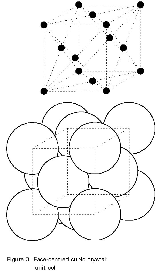
In the Fe-Co system, at approximately 50 at. % Co and below 1000 K, the random BCC A2 alpha phase transforms into the ordered simple cubic B2 structure (not shown in Figure above) of identical overall composition, where the iron atoms arrange themselves preferentially to the cube corners and the cobalt atoms to the cube centers.
 Drill Bit made from Cobalt Steel
This second-order transformation involves a relatively small amount of energy. Ordering into the cubic B2 structure is accompanied by an increase in hardness compared to the disordered (random) BCC A2 alpha phase.
According to the Fe-Mo phase diagram, the melting point of iron and molybdenum at the pressure of 101325 Pa is 1538°C and 2623°C, respectively. Note the presence of Laves phase, u-phase, R-phase, and delta-phase.
 Molybdenum Steel

Figure above Fe-Mo phase diagram shows which phases are to be expected at equilibrium for different combinations of molybdenum content and temperature.


 Alloy Suppliers
  Aluminum
  Aluminum Extrusions
  Copper-Brass-Bronze
  Nickel
  Magnets
  Stainless Steel
  Stainless Steel Tubing
  Steel Service Centers
  Titanium
  Tungsten
  Wire Rope