Introduction :
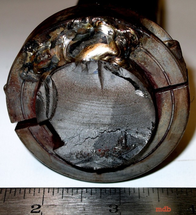
A section of a failed “rider roller” shaft was sent for failure analysis (Figure 1). This shaft is designed to ride on top of cardboard as it is being rolled. It was first installed in December 97 replacing a shaft in which cracks were observed near the ends. In March 98 a crack was observed in the centre of the roll.
 Figure 1. Photograph of “rider roller” indicating approximate point of fracture
Since no replacements were available at the time, welding was used to repair the crack. This caused the shaft to become out of round by 0. 140″. To repair this a hydraulic Jack was used at the centre of the roll to bend it back leaving a 0.040″ deflection that was corrected by machining. Nine days later, on April 11th 98 at 21: 00, the shaft broke on the key-way side while the machine was being set up at low speed. The roll usually operates at 550 meters per minute, approximately 630 RPM.
You might also like
 |
 |
 |
 |
 Alloy Suppliers
 Aluminum
 Aluminum Extrusions
 Copper-Brass-Bronze
 Nickel
 Magnets
 Stainless Steel
 Stainless Steel Tubing
 Steel Service Centers
 Titanium
 Tungsten
 Wire Rope