Introduction:
A bearing that had been in service for a year and a half was sent to undergo failure analysis (Figure 1). This bearing had been installed in the drive centrifugal pump in the R-8 plant.
 Figure 1. Photograph of bearing setup
 Figure 2. Photograph of inner ring showing spalling in groove
 Figure 3. SEM photograph of spalling, flaking and cracking, in the groove. 200X
 Figure 4. SEM photograph showing presence of 45º sheer planes. 500X
It was located on a long shaft to separate the pump from the drive due to the presence of concentrated sulphuric acid. The shaft was belt driven at about 800 RPM. No special events were noticed in the pump operation.
Observations:
The inner raceway showed severe plastic deformation around its circumference in the form of a groove, which is located above the area designed to be the ball raceway (Figure 2). Spalling, a flaking and cracking of the surface, was observed in the groove but was not evenly distributed around its circumference. Examination of the spalling using a scanning electron microscope (SEM) exposed flaking and the presence of surface cracks (Figure 3). Increased magnification of this area revealed fracture surfaces at forty-five degree angles indicating shear loads were present (Figure 4).
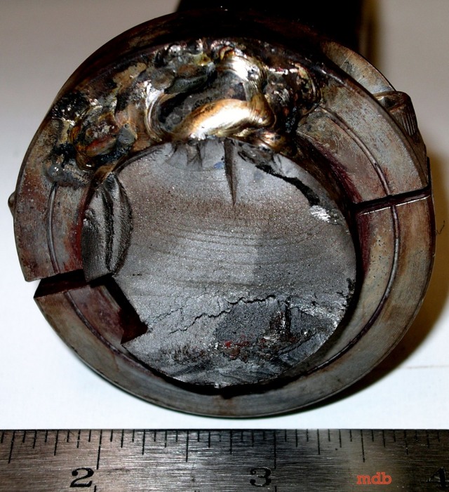
 Figure 5. Photograph of the inner ring fracture surface
 Figure 6. SEM photograph of the inner ring fracture surface showing fatigue initiating at spall in the groove. 200X
The inner raceway fracture surface is perpendicular to the groove and is located where the spalling is most severe. Beachmarks and river lines, which are characteristic of fatigue failures, revealed several initiation sites situated in the base of the groove (Figure 5). Closer examination with the SEM confirms that fatigue initiated from the spalling damage (Figure 6). Spalling was also seen to a lesser degree on the balls surfaces. The outer raceway revealed no major defects.
Material characterization and evaluation :
Both the compositions of the ball bearing and the inner raceway were found to fall within the norms for 52100 steel, AISI-SAE standards (Table 1).
Table 1. Result of chemical analysis
 Table 2. Results of microhardness tests
The microhardness measurements of both pieces are typical for this type of steel (Table 2). Surface hardness measurements for both ball and inner ring are similar, which is required by this type of application.
 Figure 7. Micrograph of cracks on the inner ring surface. 200X
 Figure 8. Microphotograph of the inner ring microstructure composed of martensite and undissolved carbides. 2% nital 200X
Microscopic examination of a cross section of the inner raceway revealed surface cracks consistent with the spalling observed (Figure 7). Etching the sample revealed a homogeneous macrostructure of a tempered martensite matrix with undissolved carbides present (Figure 8). This microstructure agrees with the chemical analysis and microhardness measurements.
 Figure 9. Micrograph of cracks on the ball surface. 100X
 Figure 10. Microphotographs of crack in a ball. 15X
 Figure 11. Microphotograph of figure 4.10 etched with 2% nital showing heterogeneous martensite structure with undissolved carbides. 15X
Microscopic examination of a quartered ball bearing also revealed surface cracks (Figure 4.9). A large crack extending towards the centre of the bearing was also found (Figure 10). The microstructure is heterogeneous, unevenly distributed tempered martinsite with undissolved carbides. The large surface crack ties along a border of the heterogeneity (Figure 4.11). Some decarburization was observed on the surface near spalling cracks.
Conclusions :
The failure was a result of vibrational fatigue initiated at spalling on the surface of the inner raceway. The spalling, which is a characteristic of contact fatigue, originated from the bearing being Installed Incorrectly or from it undergoing abnormal equiaxial radial loads in service, which caused a displacement of the inner ring. This displacement increased the axial loads causing the plastic deformation and spalling. Decarburization and uneven tempering of the balls as well as the extent of plastic deformation indicate a temperature rise.
You might also like
 |
 |
 |
 |
 Alloy Suppliers
 Aluminum
 Aluminum Extrusions
 Copper-Brass-Bronze
 Nickel
 Magnets
 Stainless Steel
 Stainless Steel Tubing
 Steel Service Centers
 Titanium
 Tungsten
 Wire Rope