Introduction :
A section of a failed “rider roller” shaft was sent for failure analysis (Figure 1). This shaft is designed to ride on top of cardboard as it is being rolled. It was first installed in December 97 replacing a shaft in which cracks were observed near the ends. In March 98 a crack was observed in the centre of the roll.
 Figure 1. Photograph of “rider roller” indicating approximate point of fracture
Since no replacements were available at the time, welding was used to repair the crack. This caused the shaft to become out of round by 0. 140″. To repair this a hydraulic Jack was used at the centre of the roll to bend it back leaving a 0.040″ deflection that was corrected by machining. Nine days later, on April 11th 98 at 21: 00, the shaft broke on the key-way side while the machine was being set up at low speed. The roll usually operates at 550 meters per minute, approximately 630 RPM.
The low carbon steel shaft was suppose to have a stainless steel weld overlay applied before installation to protect against corrosion in the mill environment. 17-4PH steel was used for this application before and failed to endure the high cycle low stress conditions.
Observations :
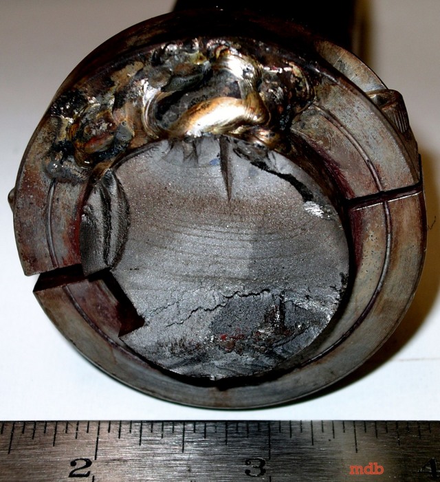
The fracture surface is characteristic of a high cycle fatigue failure caused by low torsion stresses (Figure 2). The area of final fracture is small, approximately 35% of total area, indicating that the material was adequate for the low applied stresses.
Figure 2. Photograph of fracture surface showing initiation site, beachmarks from fracture propagation, and small area of final fracture
Figure 3. Photograph of shaft surface indicating weld overlay flaw
The beachmarks (Figure 2), characteristics of fatigue that radiate from the initiation site, and the location of final fracture, being off centre, indicated that initiation did not occur evenly around the circumference of the shaft. Around the circumference of the fracture surface, a layer was observed which fractured at a 45′ angle to the plane of fracture. This is characteristic of the weld overlay. As well, there were many grooves running around the outside of the shaft that are weld overlay features (Figure 3).
Materials characterisation and evaluation :
Chemical analysis of the material revealed it to be low carbon steel. Compositions correspond to the AISI 1019 specifications (Table 1).
Tabel 1. Result of shaft chemical analysis
Using the alloy analyser, the weld overlay was found to be a low alloy steel, probably type EFe, and not stainless steel as was thought.
Table 2. Results of microhardness measurements
Microscopic examination revealed the core to have a ferrite and a coarse pearlite structure characteristics of low carbon steel (Figure 4). The weld overlay had pearlite matrix with some acicular ferrite (Figure 5). A microhardness test revealed a hard surface that gets progressively softer towards the core (Table 2). This concurs with the microstructure. The inclusions present in the core of the shaft where acceptable (Figure 6).
Figure 4. Micrograph of core microstructure composed of ferrite and pearlite. 2% nital 100X
Figure 5. Micrograph of weld overlay microstructure composed of a pearlite matrix with the presence of acicular ferrite. 2% nital 500X
Figure 6. Micrograph representing average inclusion content of the low carbon steel core. 2% nital 100X
Figure 7. Micrograph showing two inclusions found in the weld overlay 2% nital 15X
Figure 8. Micrograph showing the fracture surface initiation site. 2% nital 15X
Conclusions and Recommendations:
The failure was caused by high cycle low stress fatigue, which was initiated at inclusions in the weld overlay. For this kind of failure, when there is an absence of other defects, the surface conditions become an important factor in the prevention of crack initiation. Bending the shaft to correct its alignment probably caused decohesion of the weld inclusions encouraging microcracks to form. This would have increased local stress concentrations and the possibility of crack initiation. These inclusions probably originated from the weld being applied too quickly.
The use of a weld overlay to reconstruct existing rolls is an acceptable procedure provided the weld is applied property. This would harden the surface and thereby make the shaft more resistant to fatigue initiation at surface defects. A welding procedure should be developed that would involve the making of block samples in which the welding conditions, such as current and speed, are varied and optimised. Noranda Technology Centre can help in developing a procedure. A liquid penetrant inspection should be performed to inspect the weld overlay for any cracks or porosity.
Table 2. Fatigue related properties of selected materials
Future shafts should be made out of low alloy steel AISI-SAE 4340, heat-treated to a hardness of 35 HRC. The properties of this material fall between those of 1019 and 174PH. It will resist crack initiation better than the former, due to its higher endurance limit, and will resist crack propagation better than the latter, due to its higher fracture toughness (Table 2).
Other recommendations are :
- Avoid bending of shafts that have been surface hardened or had weld overlay applied due to the high possibility of inducing surface cracks.
- Avoid mechanical damage to the surface, such as scratches and dents, because they can act as crack initiation sites.
- Corrosion can be prevented in both cases by applying a coat of paint.
You might also like
 |
 |
 |
 |
 Alloy Suppliers
 Aluminum
 Aluminum Extrusions
 Copper-Brass-Bronze
 Nickel
 Magnets
 Stainless Steel
 Stainless Steel Tubing
 Steel Service Centers
 Titanium
 Tungsten
 Wire Rope