Resistance Spot Welding Tips
Spot welding is a technique generally used to bond metals shaped into sheets no thicker than 3 millimeters. Unlike other welding techniques, spot welding can create precise bonds without generating excessive heating that can affect the properties of the rest of the sheet. This is achieved by delivering a large amount of energy in a short time in order to create controlled and reliable welds.
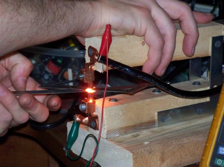
Typical spot welding machines make use of two copper alloy electrodes that are positioned over the area where the bond is to be made. The two sheets of metal that are welded are clamped by the two electrodes while a large electric current is run through them. The technique is also known as resistance spot welding, because the amount of heat delivered on the spot is directly related to the resistance between the electrodes, the amplitude of the current and the duration of the applied electric current.
Tips of Spot Welding :
- Always read and follow the safety precautions and operational instructions in your owner’s manual.
- Resistance welding is not recommended for aluminum, copper, or copper alloys. Use for steel and stainless steel only.
- For more heat (amperage output), use shorter tongs.
- For units without a heat control, tong length can be used for a control. For instance, for thin metals where you want less heat, longer tongs can be used.
- Keep in mind that longer tongs can bend, and you may lose pressure at the weld.
- For the metals being welded, make sure there is no gap between the pieces - this will weaken the weld.
- Keep the alignment of the tongs straight, so that the tips touch each other exactly. Also, maintain a proper pressure adjustment - not too much or too little pressure.
- When you need one side of the weld to have good appearance, you can flatten (machine) the tip somewhat on that side.
- Clean the tips on a regular basis, or you will lose output (amperage). Dress the tips with a proper tip dresser.
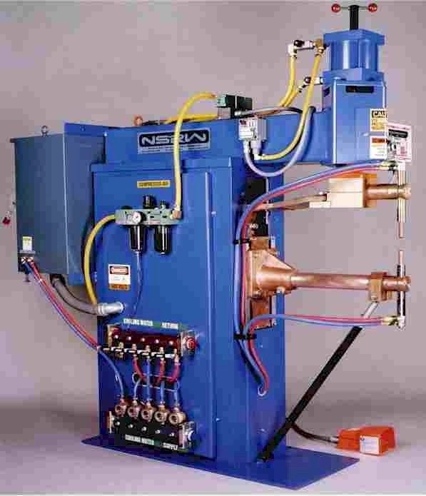 Spot Welding Machine
Spot welding parameters include :
Electrode force
The purpose of the electrode force is to squeeze the metal sheets to be joined together. This requires a large electrode force because else the weld quality will not be good enough. However, the force must not be to large as it might cause other problems. When the electrode force is increased the heat energy will decrease. This means that the higher electrode force requires a higher weld current. When weld current becomes to high spatter will occur between electrodes and sheets. This will cause the electrodes to get stuck to the sheet.
An adequate target value for the electrode force is 90 N per mm2. One problem, though, is that the size of the contact surface will increase during welding. To keep the same conditions during the hole welding process, the electrode force needs to be gradually increased. As it is rather difficult to change the electrode force in the same rate as the electrodes are “mushroomed”, usually an average value is chosen.
Diameter of the electrode contact surface
One general criterion of resistance spot-welding is that the weld shall have a nugget diameter of 5*t1/2, “t” being the thickness of the steel sheet. Thus, a spot weld made in two sheets, each 1 mm in thickness, would generate a nugget 5 mm in diameter according to the 5*t½-rule. Diameter of the electrode contact surface should be slightly larger than the nugget diameter. For example, spot welding two sheets of 1 mm thickness would require an electrode with a contact diameter of 6 mm. In practice, an electrode with a contact diameter of 6 mm is standard for sheet thickness of 0.5 to 1.25 mm. This contact diameter of 6 mm conforms to the ISO standard for new electrodes.
Squeeze time
Squeeze Time is the time interval between the initial application of the electrode force on the work and the first application of current. Squeeze time is necessary to delay the weld current until the electrode force has attained the desired level.
Weld time
Weld time is the time during which welding current is applied to the metal sheets. The weld time is measured and adjusted in cycles of line voltage as are all timing functions. One cycle is 1/50 of a second in a 50 Hz power system. (When the weld time is taken from American literature, the number of cycles has to be reduced due to the higher frequency (60Hz) that is used in the USA.)
As the weld time is, more or less, related to what is required for the weld spot, it is difficult to give an exact value of the optimum weld time. For instance :
- Weld time should be as short as possible.
- The weld current should give the best weld quality as possible.
- The weld parameters should be chosen to give as little wearing of the electrodes as possible. (Often this means a short weld time.)
- The weld time shall cause the nugget diameter to be big when welding thick sheets.
- The weld time might have to be adjusted to fit the welding equipment in case it does not fulfil the requirements for the weld current and the electrode force. (This means that a longer weld time may be needed.)
- The weld time shall cause the indentation due to the electrode to be as small as possible. (This is achieved by using a short weld time.)
- The weld time shall be adjusted to welding with automatic tip-dressing, where the size of the electrode contact surface can be kept at a constant value. (This means a shorter welding time.)
Hold time (cooling-time)
Hold time is the time, after the welding, when the electrodes are still applied to the sheet to chill the weld. Considered from a welding technical point of view, the hold time is the most interesting welding parameter. Hold time is necessary to allow the weld nugget to solidify before releasing the welded parts, but it must not be to long as this may cause the heat in the weld spot to spread to the electrode and heat it. The electrode will then get more exposed to wear. Further, if the hold time is to long and the carbon content of the material is high (more than 0.1%), there is a risk the weld will become brittle. When welding galvanized carbon steel a longer hold time is recommended.
Weld current
The weld current is the current in the welding circuit during the making of a weld. The amount of weld current is controlled by two things; first, the setting of the transformer tap switch determines the maximum amount of weld current available; second the percent of current control determines the percent of the available current to be used for making the weld. Low percent current settings are not normally recommended as this may impair the quality of the weld. Adjust the tap switch so that proper welding current can be obtained with the percent current set between seventy and ninety percent.
You might also like
| What is Spot Welding ? Spot Welding Spot welding is a technique... | Welding What is Welding ? Welding is a fabrication... | Welding Pictures Welding is a fabrication or sculptural process that... | What is Plastic Welding ? Welding Plastic Definition Plastic welding... |
 Alloy Suppliers
 Aluminum
 Aluminum Extrusions
 Copper-Brass-Bronze
 Nickel
 Magnets
 Stainless Steel
 Stainless Steel Tubing
 Steel Service Centers
 Titanium
 Tungsten
 Wire Rope