A Brief Description of the Welding Process
Welding is a joining process in which joint production can be achieved with the use of high temperatures, high pressures or both. In this lecture, only the use of high temperatures to produce a joint is discussed since this is, by far, the most common method of welding structural steels.
 Welding
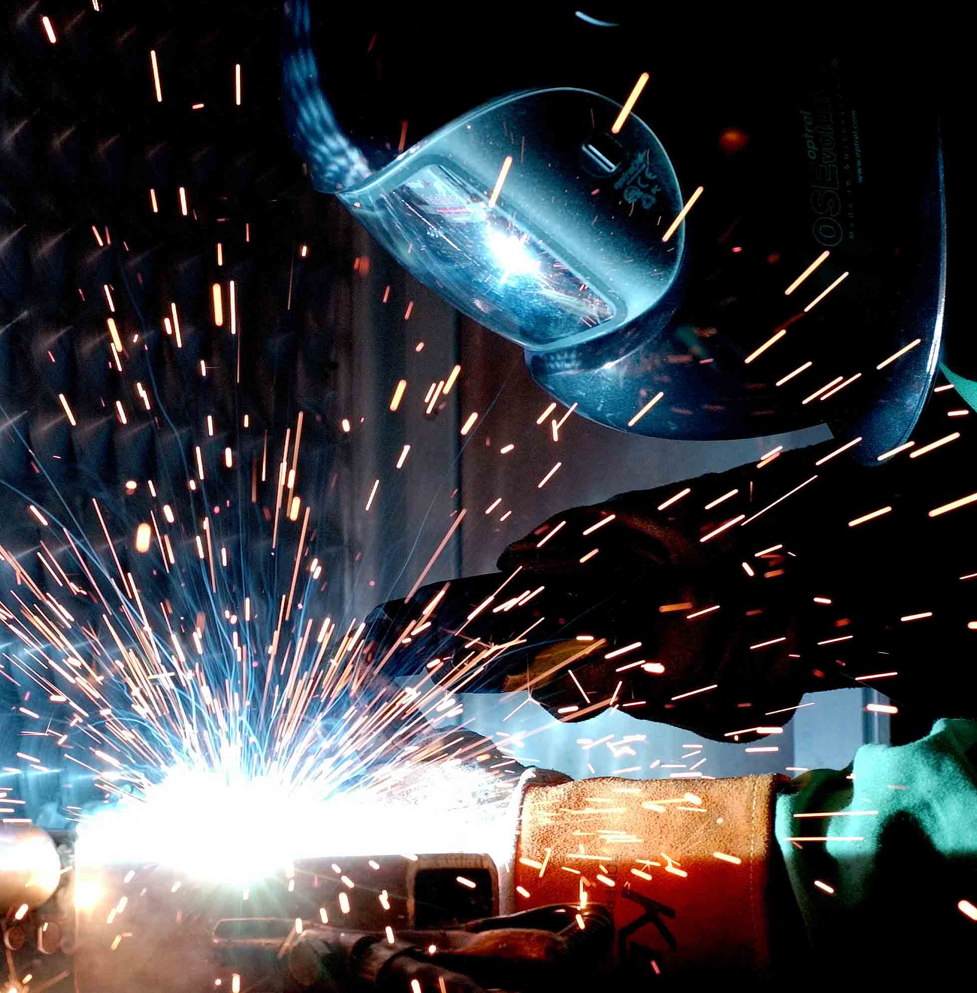
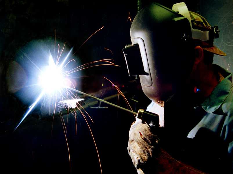
It is essentially a process in which an intense heat source is applied to the surfaces to be joined to achieve local melting. It is common for further “filler metal” to be added to the molten weld pool to bridge the gap between the surfaces and to produce the required weld shape and dimensions on cooling. The most common welding processes for structural steelwork use an electric arc maintained between the filler metal rod and the workpiece to provide the intense heat source.
If unprotected, the molten metal in the weld pool can readily absorb oxygen and nitrogen from the atmosphere. This absorption would lead to porosity and brittleness in the solidified weld metal. The techniques used to avoid gas absorption in the weld pool vary according to the welding process. The main welding processes used to join structural steels are considered in more detail below.
The Main Welding Processes
a. Manual Metal Arc welding (MMA)
In this process, the welder uses a metal stick electrode with a fusible mineral coating, in a holder connected to an electrical supply. An arc is struck between the electrode and the weld area which completes the return circuit to the electricity supply. The arc melts both the electrode and the surface region of the workpiece. Electromagnetic forces created in the arc help to throw drops of the molten electrode onto the molten area of the workpiece where the two metals fuse to form the weld pool.

The electrode coating of flux contributes to the content of the weld pool by direct addition of metal and by metallurgical reactions which refine the molten metal. The flux also provides a local gaseous atmosphere which prevents absorption of atmospheric gases by the weld metal.
There are many types of electrodes. The main differences between them are in the flux coating. The three main classes of electrode are shown below:
1. Rutile : General purpose electrodes for applications which do not require strict control of mechanical properties. These electrodes contain a high proportion of titanium oxide in the flux coating.
2. Basic : These electrodes produce welds with better strength and notch toughness than rutile. The electrodes have a coating which contains calcium carbonate and other carbonates and fluorspar.
3. Cellulosic : The arc produced by this type of electrode is very penetrating. These electrodes have a high proportion of combustible organic materials in their coating.
b. Submerged Arc Welding (SAW)
This process uses a bare wire electrode and a flux added separately as granules or powder over the arc and weld pool. The flux protects the molten metal by forming a layer of slag and it also stabilises the arc. The process is used mainly in a mechanical system feeding a continuous length of wire from a coil whilst the welding lead is moved along the joint. A SAW machine may feed several wires, one behind the other, so that a multi-run weld can be made. Submerged arc welding produces more consistent joints than manual welding, but it is not suitable for areas of difficult access.
c. Gas shielded welding
In this process, a bare wire electrode is used and a shielding gas is fed around the arc and weld pool. This gas prevents contamination of the electrode and weld pool by air. There are three main variations of this process as shown below :
1. MIG (metal-inert gas) welding - Argon or helium gas is used for shielding. This process is generally used for non-ferrous metals.
2. MAG (metal-active gas) welding - Carbon dioxide (usually mixed with argon) is used for shielding. This process is generally used for carbon and carbon-manganese steels.
3. TIG (tungsten-inert gas) - Argon or helium gas is used for shielding and the arc struck between the workpiece and a non-consumable tungsten electrode. This process is generally used for thin sheet work and precision welding.
Welded Joint Design and Preparation
There are two basic types of welded joints known as butt and fillet welds. Schematic views of these two weld types are shown in Figure 1. The actual shape of a weld is determined by the preparation of the area to be joined. The type of weld preparation depends on the welding process and the fabrication procedure.

Examples of different weld preparations are shown in Figure 2. The weld joint has to be located and shaped in such a way that it is easily accessible in terms of both the welding process and welding position. The detailed weld shape is designed to distribute the available heat adequately and to assist the control of weld metal penetration and thus to produce a sound joint. Operator induced defects such as lack of penetration and lack of fusion can be difficult to avoid if the joint preparation and design prevent good access for welding.
The Effect of the Welding Thermal Cycle on the Microstructure
The intense heat involved in the welding process influences the microstructure of both the weld metal and the parent metal close to the fusion boundary (the boundary between solid and liquid metal). As such, the welding cycle influences the mechanical properties of the joint.
The molten weld pool is rapidly cooled since the metals being joined act as an efficient heat sink. This cooling results in the weld metal having a chill cast microstructure. In the welding of structural steels, the weld filler metal does not usually have the same composition as the parent metal. If the compositions were the same, the rapid cooling could result in hard and brittle phases, e.g. martensite, in the weld metal microstructure. This problem is avoided by using weld filler metals with a lower carbon content than the parent steel.
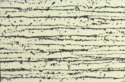
The parent metal close to the molten weld pool is heated rapidly to a temperature which depends on the distance from the fusion boundary. Close to the fusion boundary, peak temperatures near the melting point are reached, whilst material only a few millimetres away may only reach a few hundred degrees Celsius. The parent material close to the fusion boundary is heated into the austenite phase field. On cooling, this region transforms to a microstructure which is different from the rest of the parent material. In this region the cooling rate is usually rapid, and hence there is a tendency towards the formation of low temperature transformation structures, such as bainite and martensite, which are harder and more brittle than the bulk of the parent metal. This region is known as the heat affected zone (HAZ).
The microstructure of the HAZ is influenced by three factors :
- The chemical composition of the parent metal.
- The heat input rate during welding.
- The cooling rate in the HAZ after welding.
The chemical composition of the parent metal is important since it determines the hardenability of the HAZ. The heat input rate is significant since it directly affects the grain size in the HAZ. The longer the time spent above the grain coarsening temperature of the parent metal during welding, the coarser the structure in the HAZ. Generally, a high heat input rate leads to a longer thermal cycle and thus a coarser HAZ microstructure.
It should be noted that the heat input rate also affects the cooling rate in the HAZ. As a general rule, the higher the heat input rate the lower the cooling rate. The value of heat input rate is a function of the welding process parameters : arc voltage, arc current and welding speed. In addition to heat input rate, the cooling rate in the HAZ is influenced by two other factors. First, the joint design and thickness are important since they determine the rate of heat flow away from the weld during cooling. Secondly, the temperature of the parts being joined, i.e. any pre-heat, is significant since it determines the temperature gradient which exists between the weld and parent metal.
Residual Welding Stresses and Distortion
The intense heat associated with welding causes the region of the weld to expand. On cooling contraction occurs. This expansion and subsequent contraction is resisted by the surrounding cold material leading to a residual stress field being set up in the vicinity of the weld. Within the weld metal the residual stress tends to be predominantly tensile in nature. This tensile residual stress is balanced by a compressive stress induced in the parent metal.

A schematic view of the residual stress field obtained for longitudinal weld shrinkage is shown in Figure 3. The tensile residual stresses are up to yield point in magnitude in the weld metal and HAZ. It is important to note that the residual stresses arise because the material undergoes local plastic strain. This strain may result in cracking of the weld metal and HAZ during welding, distortion of the parts to be joined or encouragement of brittle failure during service.

Transverse and longitudinal contractions resulting from welding can lead to distortion if the hot weld metal is not symmetrical about the neutral axis of a fabrication. A typical angular rotation in a single V butt weld is shown in Figure 4a. The rotation occurs because the major part of the weld is on one side of the neutral axis of the plate, thus inducing greater contraction stresses on that side.
This leads to a distortion known as cusping in a plate fabrication, as shown in Figure 4b. Weld distortion can be controlled by pre-setting or pre-bending a joint assembly to compensate for the distortion or by restraining the weld to resist distortion. Examples of both these methods are shown in Figure 5.
Distortion problems are most easily avoided by using the correct weld preparation. The use of non-symmetrical double sided welds such as those shown in Figure 2e and 2i accommodates distortion. The distortion from the small side of the weld (produced first) is removed when the larger weld is put on the other side. This technique is known as balanced welding.
It is not possible to predict accurately the distortion in a geometrically complicated fabrication, but one basic rule should be followed. This rule is that welding should preferably be started at the centre of a fabrication and all succeeding welds be made from the centre out, thus encouraging contractions to occur in the free condition.
If distortion is not controlled, there are two methods of correcting it, force and heat. The distortion of light sections can be eliminated simply by using force, e.g. the use of hydraulic jacks and presses. In the case of heavier sections, local heating and cooling is required to induce thermal stresses counteracting those already present.
Residual Stress Relief
The most common and efficient way of relieving residual stresses is by heating. Raising the temperature results in a lower yield stress and allows creep to occur. Creep relieves the residual stresses through plastic deformation. Steel welded components are usually heated to a low red heat (600°C) during stress relieving treatments.
The heating and cooling rates during this thermal stress relief must be carefully controlled otherwise further residual stress patterns may be set up in the welded component. There is a size limit to the structures which can be thermally stress relieved both because of the size of the ovens required and the possibility of a structure distorting under its own weight. It is possible, however, to heat treat individual joints in a large structure by placing small ovens around the joints or by using electric heating elements.
Other methods of stress relief rely on thermal expansion providing mechanical forces capable of counteracting the original residual stresses. This technique can be applied in-situ but a precise knowledge of the location of the compressive residual stresses is vital, otherwise the level of residual stress may be increased rather than decreased. Purely mechanical stress relief can also be applied provided sufficient is available to accommodate the necessary plastic deformation.
Continue to : Weldability of Structural Steel
You might also like
 |
 |
 |
 |
 Alloy Suppliers
 Aluminum
 Aluminum Extrusions
 Copper-Brass-Bronze
 Nickel
 Magnets
 Stainless Steel
 Stainless Steel Tubing
 Steel Service Centers
 Titanium
 Tungsten
 Wire Rope