Metals often show quite acceptable properties when small smooth bar specimens are tested in tension at ambient temperature and at slow loading rates. However they fail in a brittle manner when large components are loaded or when the loading is performed at low temperatures or applied rapidly. Susceptibility to brittle fracture is enhanced if notches or other defects are present. Resistance to brittle fracture is commonly referred to as toughness.
 Toughness Curve
Metals with a body-centred cubic lattice, e.g. pure iron and ferritic steels have the unfortunate characteristic that their fracture mechanism undergoes a dramatic transition with decreasing temperature from a tough ductile mode in the higher temperature region to a brittle cleavage mode at lower temperatures. Face-centred cubic metals, e.g. copper, aluminium and austenitic steels, do not fail by cleavage under all loading conditions and at all temperatures.
Types of Fracture
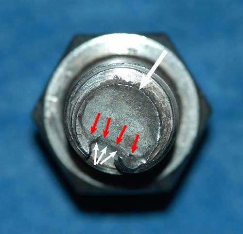
Ductile fracture involves the formation, growth and coalescence of voids. A simple analogy is the fracture of plasticene or putty containing particles of sand. The voids form around precipitates or non-metallic inclusions, Figure 1. The ductility or toughness of the material is basically dependent on the volume fraction of the void nucleating particles, i.e. the proportion of sand in the previous analogy. The amount of deformation prior to rupture and thus the toughness of the material increases with its purity.

The macroscopic orientation of a ductile fracture surface may vary from 90° to 45° to the direction of the applied stress. In thick sections most of the fracture surface tends to be oriented at 90° to the direction of the applied tensile stress. However, ductile fractures commonly have a “shear-tip” near a free boundary as the transverse stresses reduce to zero causing the plane of maximum shear to be at 45° to the direction of the applied stress.
Cleavage fracture occurs in body-centred cubic metals when the maximum principal stress exceeds a critical value, the so-called microscopic cleavage fracture stress s*f. Certain crystallographic planes of atoms are separated when the stress is sufficiently high to break atomic bonds. Crystallographic planes with low packing densities are preferred as cleavage planes. In steels the preferred change planes are the bee cube planes.
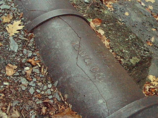
The fracture surface lies perpendicular to the maximum principal stress and appears macroscopically flat and crystalline. When viewed by eye a cleavage fracture usually displays characteristic chevron markings which point back to the origin of the fracture. When brittle fracture occurs in a large structure, such markings can be invaluable in identifying the site of crack initiation.
When viewed in the microscope, cleavage cracks can be seen to pass through the grains along preferred crystallographic planes (transgranular cleavage). If grain boundaries are weakened by precipitates or by the enrichment of foreign atoms, cleavage cracks can also propagate along grain boundaries (intergranular cleavage).
Influence of Temperature, Loading Rate, Multi-axiality and Geometry
Temperature influences fracture behaviour mainly due to its effect on yield strength and the transition from ductile to cleavage fracture. Figure 2 shows schematically the yield strength and the microscopic cleavage fracture stress as a function of temperature for a ferritic steel. The yield strength falls with increasing temperature, whereas the cleavage fracture stress is hardly influenced.

The transition temperature is defined by the intersection between the yield strength and cleavage fracture strength curves. At lower temperatures specimens fail without previous plastic deformation (brittle fracture). Somewhat above the transition temperature, cleavage fracture can still occur due to the effect of deformation induced work hardening. At higher temperatures cleavage is not possible and the fracture becomes fully ductile.

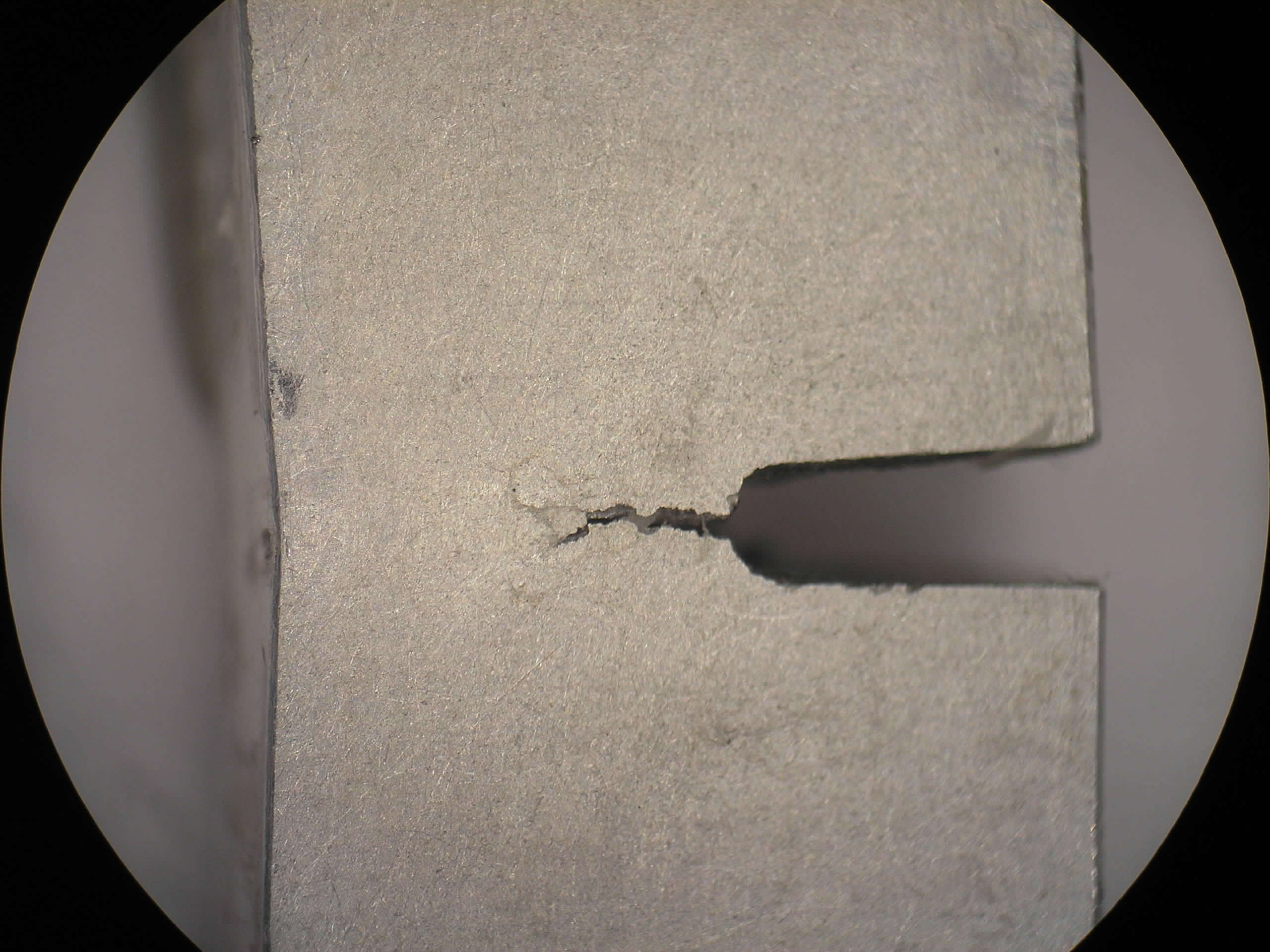
The most familiar situation in which multi-axial states of stress are encountered in steel structures is in association with notches or cracks in thick sections. The stress concentration at the root of the notch gives rise a local region of triaxial stresses even through the applied loading may be uni-directional (Figure 4).
![]()
The notched impact bend test is the most common test for the assessment of susceptibility to brittle fracture because it is inexpensive and quickly performed. 10mm square bars with a machined notch, (ISO-V or Charpy specimens), are struck by a calibrated pendulum. The energy absorbed from the swinging pendulum during deformation and fracture of the test specimen is used as a measure of the impact energy. The notch impact energy consists of elastic and plastic deformation work, fracture energy and kinetic energy of the broken pieces.

Figures 5 and 6 show the notch impact energy as a function of testing temperature. At low temperatures the failure of ferritic steels occurs by cleavage fracture giving a lustrous crystalline appearance to the fracture surface. At high temperatures failure occurs by ductile fracture after plastic deformation. In the transition range small amounts of ductile fracture are found close to the notch but, due to the elevated stresses near the crack tip, the fracture mechanism changes to cleavage. Throughout the transition range the amount of cleavage fracture becomes less and the notch impact energy rises as the testing temperature increases.
![]()
In order to characterise the transition behaviour, a transition temperature is defined as the temperature at which:
- a defined value of the notch impact energy is reached (eg. T27J, T40J),
- half of the maximum impact energy value is reached (T50%), or
- 50% ductile fracture is observed on the fracture surface (FATT 50: Fracture Appearance Transition Temperature, 50% ductile fracture).
The impact energy values obtained show a high amount of scatter in the transition area because here the results depend on the local situation ahead of the crack tip. Beyond this area, scatter becomes less because there is no change of fracture mechanism.
The notched impact bend test gives only a relative measure of toughness. This measure is adequate for defining different grades of toughness in structural steels and for specifying steels for well established conditions of service. For the assessment of known defects and for service situations where there is little experience of brittle fracture susceptibility, a quantitative measure of toughness which can be used by design engineers is provided by fracture mechanics.
Continue to “Fracture Toughness“…
You might also like
 |
 |
 |
 |
 Alloy Suppliers
 Aluminum
 Aluminum Extrusions
 Copper-Brass-Bronze
 Nickel
 Magnets
 Stainless Steel
 Stainless Steel Tubing
 Steel Service Centers
 Titanium
 Tungsten
 Wire Rope