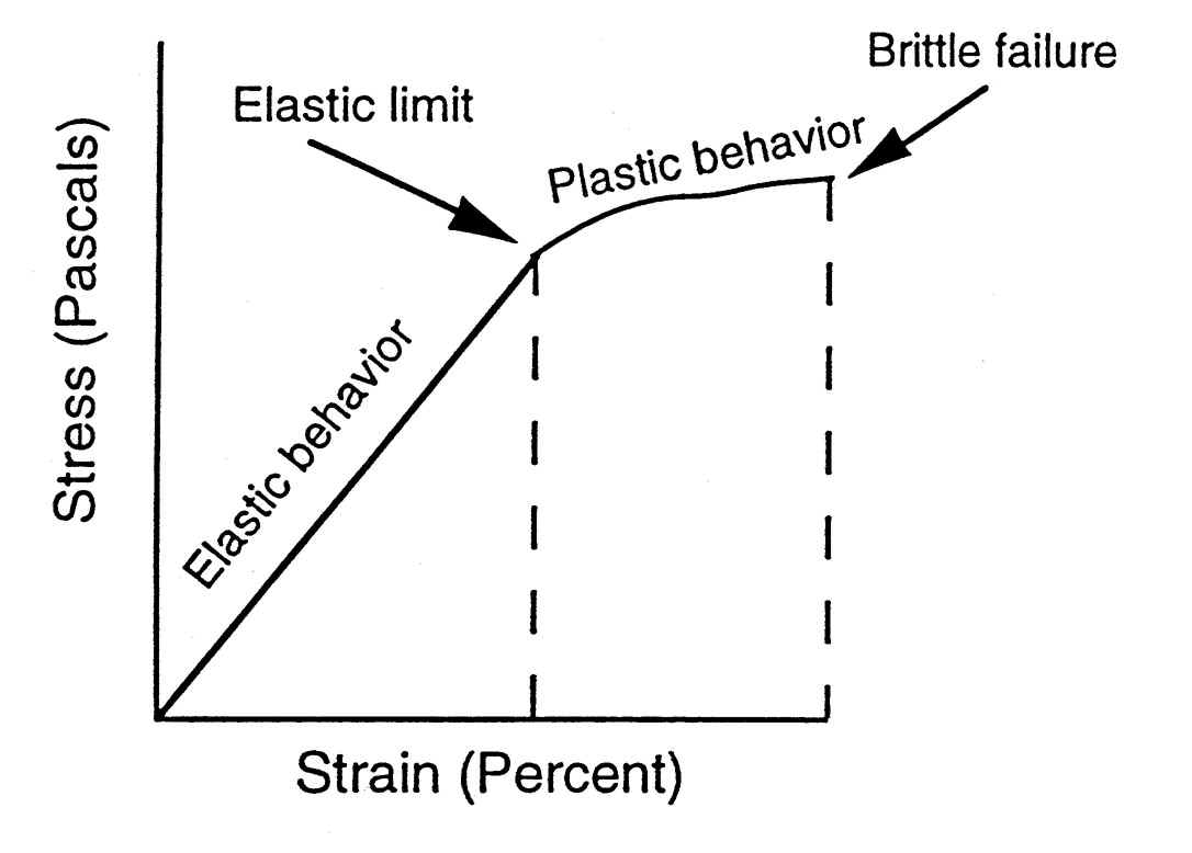
The basis of a fracture mechanics safety analysis is the comparison between the crack driving force in a structure and the fracture toughness of the material evaluated in small scale tests. The application of one of the concepts depends on the overall behaviour of the structure which may be linear-elastic (K-concept) or elastic-plastic (CTOD- or J-Integral-concepts). For a safe structure the crack driving force must be less than the fracture toughness.
 Fracture Mechanic
In general the toughness values of the material are evaluated according to existing standards. The crack driving force can be calculated on the basis of analytical solutions (K-concept), empirical or semi-empirical approaches (CTOD-Design-Curve approach, CEGB-R6-procedures) or using numerical solutions (indirectly: EPRI-handbook, directly: finite-element calculations). The different methods are explained briefly below:
- K-concept
The K-concept can be applied in the case of linear-elastic component behaviour. The crack driving force, the so-called stress intensity factor KI, defined in Section 1.4, has been evaluated for a large range of situations and calculation formulae are for example given in the stress-analysis-of-cracks handbook.
Usually the critical fracture toughness KIc of the material is evaluated according to the ASTM standard E399 or the British Standard BS5447. Brittle failure can be excluded as long as:
KI < KIc
For a given fracture toughness the critical crack length or stress level can be calculated from:
ac =
sc =
- CTOD-Design-Curve approach
A critical crack length or stress level can be determined using the limit curve of the CTOD-Design-Curve approach for the driving force assessment together with measured values of CTODcrit for the material. The limit curve has been adopted by standards, e.g. the British Standard BS-PD 6493. The latest version of the limit curve is shown in Figure 11 and can be used for:
2a/W £ 0,5 and snet £ sYS.

Analysis can only be performed under global elastic conditions (snet £ sYS) although local plastic deformation may occur in front of a crack tip which is accounted for in the CTOD-value of the material.
- CEGB-R6-routines
The CEGB-R6-routines can be used to assess the safety of structures for brittle and ductile component behaviour. The transition from linear-elastic to elastic-plastic behaviour is described by a limit curve in a failure analysis diagram (Figure 12). The ordinate value Kr can be regarded as any of three equivalent ratios of applied crack driving force to material fracture toughness as follows:

Kr = =
=
- Other methods
Other methods are emerging. The Electrical Power Research Institute (EPRI) in New York has used a detailed analysis by finite elements to determine limiting J contour values for standard geometries. Alternatively the J contour values may be obtained by direct finite element analysis of the particular situation.
During the last 20 years, large flat tensile specimens, so-called wide plates, have been used to simulate a relatively simple detail of a tension loaded large structure. A main objective of wide plate testing is the evaluation of the deformation and fracture behaviour of a specimen under service conditions. The second reason for this kind of test is the application of test results for the development and checking of failure assessment methods, e.g. fracture mechanics methods.

Wide plate tests require testing facilities with high loading capacities due to the fact that such tests are usually carried out at full thickness. The maximum dimensions of wide plates tested on large test rigs with a load capacity of up to 100MN are as follows:
- specimen width W £ 3000mm
- specimen thickness to £ 300mm
- specimen length l £ 5000mm
Figure 9 shows different types of specimen containing discontinuities for tests on the base metal or welded joints. The discontinuities may be through-thickness or surface notches or cracks. The configuration of the plate is usually chosen according to the specific structural situation to be assessed.
Stress or strain criteria can be used as safety criteria which must be fulfilled to assure the safety of a specific structural element. The production of a given amount of overall strain is in some cases used as the failure criterion. The gross-section-yielding concept requires that gross-section-yielding (GSY) occurs prior to fracture. Based on this concept, wide plates with different crack lengths are tested under similar loading conditions to determine a critical crack length just fulfilling the GSY-criterion. Figure 10 shows the ratio of the maximum gross-section stress in the structure to ultimate tensile strength as a function of the crack length ratio 2a/W of centre-notched wide plates.

The upper limit line describes the theoretical maximum stress, if the ultimate tensile strength is reached in the cross-section containing the discontinuity. All test results show lower values than are implied by the theoretical line, resulting from the important influence of toughness in the presence of discontinuities. Only in the case of infinite toughness can the theoretical line be reached.
The intersection of the experimentally determined curve and the yield strength line marks the critical crack length ratio 2ac/W. As long as the 2a/W ratio is smaller than the critical ratio, the GSY-criterion is fulfilled. Unfortunately, the critical 2ac/W ratio depends strongly on the dimensions of the crack and the plate, so that different types of cracked components always require a series of specific wide plate tests. This concept is therefore only used if other concepts cannot be applied.
Continue to “Optimal Combination of STRENGTH and TOUGHNESS“
You might also like
 |
 |
|
 |
 Alloy Suppliers
 Aluminum
 Aluminum Extrusions
 Copper-Brass-Bronze
 Nickel
 Magnets
 Stainless Steel
 Stainless Steel Tubing
 Steel Service Centers
 Titanium
 Tungsten
 Wire Rope