A is generally said to be brittle if it cannot be deformed to any appreciable degree prior to fracture. This behaviour does not imply that the ultimate tensile strength measured on a smooth specimen during a tensile test is low. On the contrary, the opposite phenomenon is usually observed. Hardening treatments which aim to increase strength are usually accompanied by a dramatic degradation of ductility and tend to enhance brittleness.
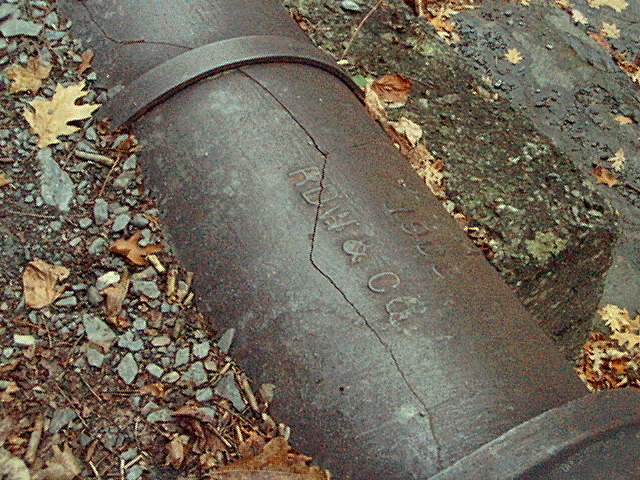
 Brittle Failure Curve
Brittleness is neither an absolute nor a simple concept. As a rule, the susceptibility to brittle behaviour in a given material is increased by:
- the lower the temperature to which it is exposed.
- the more rapid the loading to which it is submitted.
- the more disturbed the stress distribution it experiences.
Brittleness is influenced by ductility, i.e. the capacity of a material to strain plastically, and by strain-hardenability, i.e. the property of developing a higher strength while undergoing plastic deformation.
Ductility can easily be appraised in a bend test under strain-controlled conditions where the material is bent round a mandrel with large plastic strains being induced in the outer fibres of the specimen (Figure 1). The more ductile material can be bent round a smaller mondrel without fracture.
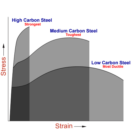
Strain-hardenability is appraised in a tensile test and is quantified by the slope of the stress-strain curve in the plastic regime. Strain hardening governs the amount of uniform elongation a material may undergo before necking or fracturing (Figure 2).
A material showing no ductility is intrinsically brittle and produces, even in a defect-free situation, negligible plastic elongation during a tensile test and no strain hardening. Such a material is glass.
Steel usually exhibits ductile behaviour in the tensile test and the presence of some defect is necessary to induce brittleness. The defect may be a geometrical discontinuity with sharp edges constituting a stress raiser, or an area in which the mechanical properties are locally impaired such as the heat affected zone of a weld, or a region of local plastic deformation which may undergo subsequent strain ageing. Often, both geometrical and metallurgical defects are present together; weldments may undergo lack of penetration or contain cold cracks, while punches or shears may create burrs or notches. A large embrittling effect may thus be induced.
Should the ductility of the metal at the tip of the notch be very poor, then no possibility would exist to blunt the notch by plastic deformation. The result would be a brittle failure occurring at a load which can be calculated from linear elastic theory as a function of the component dimensions, the notch size and the toughness characteristics of the metal.
In the case where a degree of ductility is available, crack blunting occurs and is reflected in a degree of crack opening. The fracture behaviour is then significantly influenced by the strain hardenability of the metal. If little strain hardening is available, then the crack may propagate through the component at a rather constant stress level, either by ductile tearing or brittle cracking.
Different fracture behaviour can be observed with a ductile metal which is capable of sustained strain hardening since propagation of the defect after crack blunting requires an increasing load to be applied to the component. Such conditions give rise to stable crack propagation.
FRACTURE MECHANICS CONCEPTS AND TESTING PROCEDURES
Several specific tests have been developed to assess the fracture behaviour of materials in various loading conditions and defect configurations. It is not the scope of this lecture to detail the testing procedures or review the methods for derivation of toughness values. However, it is worth listing the main concepts and types of test as well as the assumptions on which they rely.
Fracture Mechanics has been approached in a rigorous way on the basis of linear elastic theory which led to the well-known concept of stress intensity factor, KI. This parameter defines completely the stress field in the vicinity of a crack. Fracture occurs when it attains a critical value which is a characteristic of the material. The main assumption of this theory is the presence of minimal plastic strain at the crack tip. With steel, such conditions may be met with very high strength products or when the thickness is large. Table 1 defines the basic equations of Linear Elastic Fracture Mechanics (LEFM) together with the conditions of applicability.
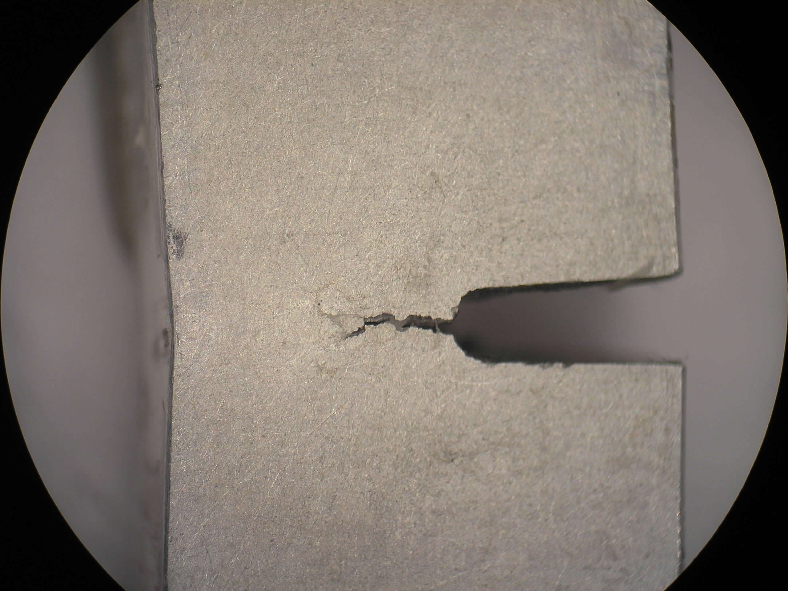
In many circumstances significant plasticity takes place at the crack front prior to failure and crack opening may be observed before fracture initiation (Figure 3). The concept of Crack Opening Displacement (COD) or more precisely (CTOD) defines the amplitude of the crack tip plasticity under a given stress situation. Fracture initiates when this parameter reaches a critical value (dcrit) which is a characteristic of the material and a measurement of its toughness.
It is important to mention that both the CTOD and the J concepts are designed to assess situations in which fracture occurs in the elasto-plastic region, but imply nevertheless a relatively small extent of plastic strain at the crack tip. To assess the risk of failure by brittle fracture, means have been provided to estimate the CTOD or J values in a large structure containing a defect, as a function of the overall applied loads. These estimated values are then compared with the critical failure values for the relevant material. A well known design curve for such fitness-for-purpose analysis is based on the CTOD approach (Figure 4).
All the above procedures normally require that the product be tested with its full thickness so as to derive a suitable toughness index. Although this condition may involve test specimens having rather large dimensions, it can never be considered as appraising the overall fracture behaviour of a structural component. Therefore, the relevance of the transferability of the test data for the appraisal of large structures has to be verified by comparing the computed fracture behaviour to that experimentally observed during tests on a very large piece whose size is similar to the parts of a real structure.
The Wide Plate test has been designed with this aim. It involves tensile testing, possibly at lowered temperature, of a wide specimen (1m wide for instance) containing deliberate through-thickness or surface cracks. A convenient evaluation of performance in the Wide Plate test is provided by the Yield criterion. When full yield occurs, then all sections of the specimen, even those not affected by the defect, develop plastic strains so that the overall elongation is sufficient to prevent a sudden failure. Full yield also ensures that the structure can reach its maximum elastic design load, i.e. the product of the material yield stress and the gross section, as if it were not affected by the defect, which is an obvious asset for safety. A critical defect length can be defined above which the criterion can no longer be fulfilled; then only net section yielding or contained yielding are achieved. Table 2 summarises the main concepts relating to the Wide Plate test.
There are situations in which resistance to failure is not governed by toughness but by the load bearing capability of the net section in the part affected by a defect. This situation may occur with quite ductile materials affected by cracks. Plastic collapse corresponds to the achievement of unlimited displacements in the net section when the applied load induces a net section stress equal to the material flow stress. A ratio Sr may be defined to express the safety against plastic collapse for a given loading condition. It is sometimes more convenient to use the material yield stress as a reference and think in terms of plastic yield load. A ratio Lr is then considered. Table 3 defines the parameters.
Although the assumptions associated with Linear Elastic Fracture Mechanics and Plastic Collapse lead to quite opposite fracture mechanisms, both concepts may actually apply to the same material and even the same structure depending on the defect size. Figure 5 illustrates this situation for the simple example of a wide plate containing a through-thickness defect. For small defect sizes the lowest fracture resistance is dictated by plastic collapse concepts, whereas for larger defects the lowest fracture resistance is obtained from linear elastic theory.
REFERENCES
- Eurocode 3: “Design of Steel Structures”: ENV 1993-1-1: Part 1.1, General rules and rules for buildings, CEN, 1992.
- Brock, D., Elementary engineering fracture mechanics, Martinus Nijhorff Publishers, 1987.
- Garwood, S. J., A crack tip opening displacement (CTOD) method for the analysis of ductile materials, ASTM STP 945, June 1985.
- Rice, J. R., A path independent integral and the approximate analysis of strain concentrations by notches and cracks, Trans. ASME, J. Appl. Mech. 1968, 35 379-386.
- Soete, W. and Denys, R., Evaluation of butt welds based on a strain criterion, Revue de la Sodure, Lastijd schrift, No. 4, 1975.
- Milne, I., Ainsworth, R. A., Dowling, A. R., Stewart, A. T., Assessment of the integrity of structures containing defects, CEGB document R/H/R6 - Revision 3, May 1986.
- EN 10025: Hot Rolled Products of Non-alloy Structural Steels and their Technical Delivery Conditions, British Standards Institution, 1990.
- EN 10113-1: Hot Rolled Products of Weldable Fine Grain Structural Steels Part 1: General Delivery Conditions, British Standards Institution, 1993.
- ENV 10113-2: Hot Rolled Products of Weldable Fine Grain Structural Steels Part 2: Delivery Conditions for Normalized/Normalized Rolled Steels, British Standards Institution, 1993.
- ENV 10113-3: Hot Rolled Products of Weldable Fine Grain Structural Steels Part 2: Delivery Conditions for Normalized/Normalized Rolled Steels, British Standards Institution, 1993.
- Sanz, G., Essai de mise au point d’une mthode quantitative de choix des aciers vis-á-vis du risque de rupture fragile, Revue de Mtallurgie - CIT, Juillet 1980.
- George, M., A method for steel selection, Document IIW-IXF.
- Defourny, J., D’Haeyer, R., Leroy, V., A metallurgical approach of the parameters affecting the fracture behaviour of base metal and welded components, IIW document IX-1607-90/X-1206-90.
- Sedlacek, G., Bild, J., Hensen, W., Background document for Chapter 3 of Eurocode 3 “Design Against Brittle Fracture”, Aachen 1990.
- Brozzetti, J., Sedlacek, G., Hensen, W., Fondements des regles de l’Eurocode 3 en vue de se garantir du risque de rupture fragile, Construction Mtallique, no. 1, 1991.
- Guidance on methods for assessing the acceptability of flaws in fusion welded structures, PD6493: 1991, BSI.
- Burdekin, F. M., Materials selection for welded structural steelwork in Engineering Design in welded constructions, Pergamon Press, 1992.
- de Meester, B., The brittle fracture safe design of welded constructions, Welding in the world.
- Sanz, G., La rupture des aciers, fascicule 2, Collection IRSID OTUA.
- Dahl, W., Hesse, W., Krabiell, A., Zur WVerfestigung von Stahl und dessen Einflub auf die Kennwerte des Zugversuchs; Stahl und Eisen 103 (1983), Heft 2, Seite 87-90.
You might also like
 |
|
 |
 |
 Alloy Suppliers
 Aluminum
 Aluminum Extrusions
 Copper-Brass-Bronze
 Nickel
 Magnets
 Stainless Steel
 Stainless Steel Tubing
 Steel Service Centers
 Titanium
 Tungsten
 Wire Rope